


Next: RTL data transfer power
Up: Data transfer wires
Previous: Local power model
A DPU's output network consists of the RTL interconnect components
connecting its output to the inputs of other DPUs. A data transfer
between two DPUs is assumed to be center-to-center and rectilinear
for the purpose of simplicity. [] shows that more than
95% of wires in an ASIC are routed in the Manhattan way,  ,
without any detour from the shortest route. We therefore assume
all data transfers are routed in the Manhattan way. A bus-based
architecture shares the output networks among DPUs through busses.
Since sharing output networks imposes a high performance and power
penalty [46], we assume that output networks are not
shared in the multiplexer-based architecture we use. Nevertheless,
it is still possible to share wires within one output network.
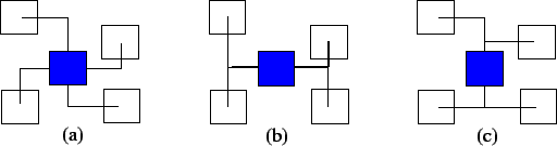
Fig. 7(a) shows one DPU sending data to four other
DPUs through a fully dedicated output network. If the DPU sends
all the data to all the dedicated data transfer wires,
minimization of total power consumption in the output network will
be the same as minimization of the total wire length in the output
network. Therefore, a minimum spanning tree (MST) output network
in the Steiner tree style [51] would have the
least interconnect power consumption. However, if we take steps to
reduce the SSA in the interconnect, minimal total length does not
necessarily imply minimal total power consumption because it is
hard to distinguish between dedicated and shared interconnects in
the case of an MST. We introduce a trunk-branches style
Steiner tree for the output network as shown in
Figs. 7(b) and 7(c). The DPU sends all
the data to a trunk which is either vertical or horizontal. All
the other DPUs receive data from the shared trunk through
perpendicular dedicated branches. Whether the trunk is vertical or
horizontal depends on which one yields smaller power consumption.
In Section V, we will compare three output network
styles, fully dedicated, optimal total length shared and
trunk-branches, in detail. We also assume all metal layers have
the same capacitive parameters as the metal layer one. This
assumption slightly underestimate interconnect power but obviates
layer assignment and accelerate power estimation.
,
without any detour from the shortest route. We therefore assume
all data transfers are routed in the Manhattan way. A bus-based
architecture shares the output networks among DPUs through busses.
Since sharing output networks imposes a high performance and power
penalty [46], we assume that output networks are not
shared in the multiplexer-based architecture we use. Nevertheless,
it is still possible to share wires within one output network.
Fig. 7(a) shows one DPU sending data to four other
DPUs through a fully dedicated output network. If the DPU sends
all the data to all the dedicated data transfer wires,
minimization of total power consumption in the output network will
be the same as minimization of the total wire length in the output
network. Therefore, a minimum spanning tree (MST) output network
in the Steiner tree style [51] would have the
least interconnect power consumption. However, if we take steps to
reduce the SSA in the interconnect, minimal total length does not
necessarily imply minimal total power consumption because it is
hard to distinguish between dedicated and shared interconnects in
the case of an MST. We introduce a trunk-branches style
Steiner tree for the output network as shown in
Figs. 7(b) and 7(c). The DPU sends all
the data to a trunk which is either vertical or horizontal. All
the other DPUs receive data from the shared trunk through
perpendicular dedicated branches. Whether the trunk is vertical or
horizontal depends on which one yields smaller power consumption.
In Section V, we will compare three output network
styles, fully dedicated, optimal total length shared and
trunk-branches, in detail. We also assume all metal layers have
the same capacitive parameters as the metal layer one. This
assumption slightly underestimate interconnect power but obviates
layer assignment and accelerate power estimation.
Figure 7:
Different topologies of an output network: (a) fully
dedicated,
and trunk-branches output network with the trunk being
(b) horizontal, and (c) vertical.
 |
Next: RTL data transfer power
Up: Data transfer wires
Previous: Local power model
Lin Zhong
2003-10-11